

- Key Takeaways
- What Is a Highway Guardrail System?
- Highway Guardrail Components at a Glance
- 1. Rail Element: W-Beam and Thrie-Beam Guardrail
- 2. Guardrail Posts
- 3. Blockouts (Offset Blocks or Spacer Blocks)
- 4. Rail Splices and Splice Bolts
- 5. Post Bolts, Washers and Backup Plates
- 6. End Terminals and Anchors
- 7. Transition Sections, Rubrails and Terminal Connectors
- 8. Special-Purpose Components
- How Highway Guardrail Components Work Together in a Crash
- Guardrail Components Under EN 1317
- Component Checklist for Buyers and Installers
- Frequently Asked Questions
- Sourcing Highway Guardrail Components
- References
Highway guardrail components are the parts that make a guardrail work as one system: the steel rail (W-beam or thrie-beam), the posts, the blockouts, the splice and post bolts, the end terminals and anchors, and the transition sections that connect guardrail to bridges or concrete barriers. None of these parts protects a vehicle on its own. U.S. Federal Highway Administration (FHWA) guidance states that the primary mechanism that lets guardrail redirect a vehicle is tension developed in the rail element, and the other components keep the rail at the right height, continuous and anchored so that this tension can develop.[1]
This guide explains what each component is, what it does during a crash, and which specifications buyers and engineers normally check. It is based on FHWA publications, the AASHTO M 180 rail specification, the AASHTO-ARTBA-AGC Task Force 13 hardware guide, the Washington State DOT Design Manual and the EN 1317 framework used in Europe. Sources are listed at the end.
Key Takeaways
- A strong-post W-beam guardrail is a semi-rigid barrier: it resists an impact through the tensile and bending stiffness of the rail plus the bending or shearing resistance of the posts.[6]
- The rail carries tension; posts hold it at the correct height and limit deflection; blockouts keep wheels away from posts; splices keep the rail continuous; terminals and anchors give the rail something to pull against.[1][6]
- Rail height matters: in full-scale tests a 25 in (635 mm) W-beam did not contain the design pickup-truck impact.[1] The modern Midwest Guardrail System (MGS) sets the top of rail at a nominal 31 in (787 mm).[2]
- Guardrail rail steel in the U.S. is specified by AASHTO M 180: Class A is 2.67 mm (0.105 in) and Class B is 3.43 mm (0.135 in) base-metal thickness.[5]
- Crash performance belongs to the tested system, not to individual parts. FHWA warns against interchanging parts that are unique to different manufacturers’ end treatments.[1][10]
What Is a Highway Guardrail System?
A highway guardrail system is a longitudinal roadside barrier that shields motorists from hazards such as steep slopes, bridge piers or opposing traffic. In many export markets the same product is called a crash barrier or road safety barrier. The most common type is the strong-post W-beam guardrail, which WSDOT describes as a semi-rigid barrier made of wood or steel posts, a steel rail and blockouts that hold the rail away from the posts.[6]
When a vehicle strikes the rail, the rail deflects and stretches between its anchored ends. FHWA notes that strong posts “contribute to smooth redirection by limiting the amount of deflection and providing consistent stiffness along the rail to prevent pocketing.”[1] WSDOT describes pocketing as a vehicle being caught in the pocket of a deflected barrier and directed into a more rigid object.[6]
Because the system works as a chain, a weak link anywhere (a missing splice bolt, an unanchored end, a post set too high) reduces the performance of the whole run. That is why each component below has its own specification.
Highway Guardrail Components at a Glance
| Component | What it is | Main function | Typical reference |
|---|---|---|---|
| Rail element (W-beam / thrie-beam) | Corrugated galvanized steel beam, 3.81 m or 7.62 m effective length | Develops tension and bending resistance that redirects the vehicle | AASHTO M 180[5] |
| Guardrail post | Steel wide-flange (W6x9 / W6x8.5) or timber post driven into soil | Holds the rail at design height, limits deflection, provides even stiffness | TF13 PWE06; FHWA[4][1] |
| Blockout (offset block, spacer) | Timber, composite or steel block between rail and post | Spaces the rail away from the post to minimize wheel snagging | TF13 PDB10; FHWA[4][1] |
| Splice and splice bolts | Overlapping rail ends joined by eight 5/8 in button-head bolts | Keeps the rail continuous so tension passes from panel to panel | FHWA; TF13 FBB01[1][4] |
| Post bolt, washer and backup plate | 5/8 in button-head bolt and recessed nut (no washer under the bolt head); 1 ft W-beam backup plate where specified | Fixes the rail to the post at the right height | FHWA[1] |
| End terminal / end treatment | Crash-tested assembly at an exposed upstream end | Avoids spearing on end-on hits and anchors the rail for side hits | FHWA; MASH[1][7] |
| Anchor | Cable, bearing plate, foundation post or buried end | Develops tensile strength throughout the run | WSDOT[6] |
| Transition section | Stiffened length of guardrail (nested rail, closer and larger posts, rubrail) next to a rigid barrier | Prevents pocketing and snagging at a bridge rail or concrete barrier | FHWA; WSDOT[1][6] |
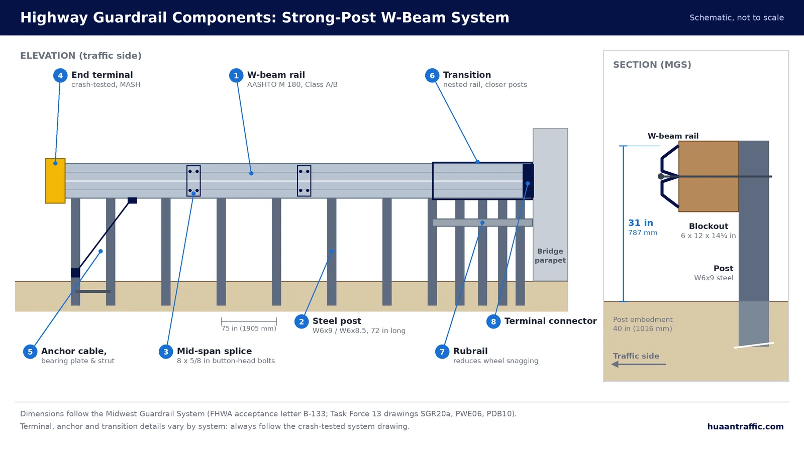
1. Rail Element: W-Beam and Thrie-Beam Guardrail
The rail element is the highway guardrail component that vehicles actually contact: a corrugated steel beam. A W-beam has two corrugations and is about 311 mm (12¼ in) wide and 83 mm deep; a thrie-beam has three corrugations and is about 508 mm (20 in) wide.[11] AASHTO M 180 lists the effective length of a beam section as 3.8 m or 7.6 m (12.5 ft or 25.0 ft) and covers both the W-beam and thrie-beam shapes.[5]
Function: the rail converts the vehicle’s sideways motion into tension along the barrier. It also has to be straight and undamaged: FHWA warns that energy-absorbing terminals depend on the column strength of the rail, so even small dents near the impact head can stop the terminal from working as designed.[1]
Thrie-beam presents a taller rail face than W-beam (about 508 mm versus 311 mm). WSDOT uses W-beam-to-thrie-beam transitions where guardrail connects to thrie beam on bridges, and lists thrie-beam retrofits as an economical way to improve the strength and redirection of an existing bridge barrier.[6] For product details see our W-beam guardrail and thrie-beam guardrail pages.
AASHTO M 180 Classes and Coating Types
In AASHTO M 180, the class defines the steel thickness and the type defines the corrosion protection.[5]
| M 180 designation | Definition (AASHTO M 180-18) |
|---|---|
| Class A | Base-metal nominal thickness 2.67 mm (0.105 in), commonly called 12 gauge |
| Class B | Base-metal nominal thickness 3.43 mm (0.135 in), commonly called 10 gauge |
| Type I | Zinc-coated, 550 g/m² (1.80 oz/ft²) total both sides, minimum single-spot |
| Type II | Zinc-coated, 1100 g/m² (3.60 oz/ft²) total both sides, minimum single-spot |
| Type III | Beams to be painted |
| Type IV | Beams of corrosion-resistant (weathering) steel |
| Type V / VI | Zinc-6% aluminum-3% magnesium alloy coated: 245 g/m² (0.80 oz/ft²) for Type V, 305 g/m² (1.00 oz/ft²) for Type VI, total both sides, minimum single-spot |
A typical state specification asks for Class A or Class B rail with a Type II coating. Indiana DOT, for example, expects guardrail on site to be physically stamped with “M180” and asks inspectors to check which edition of M 180 the certification covers.[8] NCDOT requires backup plates to be the same class and type as the full-length beams, and end or buffer sections to be at least as thick as the beam they are attached to.[9]
2. Guardrail Posts
Guardrail posts are the highway guardrail components that hold the rail at its design height and transfer impact load into the soil. In the U.S. the standard strong post is a steel wide-flange section, W6x9 (W150x13.4), with W6x8.5 accepted as an equivalent; timber posts (typically 6 x 8 in or 8 x 8 in) are the main alternative.[4][1] The Task Force 13 drawing for the 72 in (1829 mm) steel post calls for AASHTO M 270 Grade 250 or ASTM A36 steel, hot-dip galvanized to AASHTO M 111 (ASTM A123) after cutting and drilling.[4]
Function: posts must be strong enough to keep the rail up and limit deflection, yet able to rotate in the soil when hit. WSDOT states that guardrail posts “should be able to rotate when the rail is impacted”, and requires leave-outs (areas with no rigid material) when posts are installed in asphalt or concrete pavement.[6] FHWA recommends a longer post (7 ft or more) in front of a fill slope where there is less than 1 ft of relatively flat ground behind the post.[1]
Post spacing and embedment are part of the tested design. The MGS uses 6 ft (1829 mm) steel posts on 75 in (1905 mm) centers, with the post raised about 4 in compared with older W-beam layouts to reach the higher rail.[2] The MGS was also tested with quarter-post spacing (18.75 in) and analyzed at half-post spacing (37.5 in); closer spacing reduces the working width needed in front of a rigid obstacle.[2]
Guardrail systems used in other markets may specify different post profiles. Huaan Traffic manufactures C-posts, U-posts, Sigma posts, H-posts and Z-posts; the correct profile is always the one shown on the drawing of the system that was crash-tested for your project.
3. Blockouts (Offset Blocks or Spacer Blocks)
Among highway guardrail components, the blockout is the block bolted between the rail and the post. FHWA describes its purpose simply: it is used “to space the rail away from the post to minimize snagging.”[1] WSDOT likewise lists “blocking the rail away from the posts” as one of the ways to prevent snagging or spearing.[6] Snagging means a wheel or part of the vehicle catches on a post as it moves along the barrier.
The MGS and WSDOT Type 31 systems use blockouts that extend 12 in from the post.[6] The MGS standard timber blockout (TF13 designator PDB10) measures 6 x 12 x 14¼ in (152 x 305 x 362 mm), must have a stress grade of at least 1200 psi and is preservative-treated to AASHTO M 133 after cutting and drilling.[4][2] The Task Force 13 component list also includes proprietary composite (plastic) blockouts intended for specific systems.[4]
Two installation details matter. Wood blockouts on wood posts should be toenailed to stop them rotating, and steel blockouts should only be used where the agency allows them; FHWA permits steel blocks on steel posts for repairs at posted speeds of 45 mph or less.[1] Read more in our article Why install spacer blocks between guardrail panels and posts?
4. Rail Splices and Splice Bolts
Rail is supplied in 12 ft 6 in or 25 ft effective lengths[5], so the panels must be joined at splices. FHWA requires eight 5/8 in splice bolts in each rail connection; the standard hardware is a 5/8 in x 1¼ in galvanized button-head bolt with a recessed nut.[1]
Function: the splice carries the full rail tension from one panel to the next. FHWA lists “eight 5/8-in splice bolts in each rail connection” and “no tears” as the conditions for tension capability to be intact.[1]
Direction matters. Rail elements must be lapped in the direction of traffic, with the upstream (approach) rail in front of the downstream rail.[1] WSDOT lists lapping splices in the direction of traffic as one of the measures that prevents vehicle snagging or spearing.[6] In the MGS, splices were moved from the posts to mid-span between posts.[2][6]
The Task Force 13 drawing for the oval-shoulder button-head bolt (FBB01-05) specifies 5/8-11 (M16x2) threads, ASTM A307 Grade A material (60 ksi / 400 MPa tensile strength), and zinc coating to AASHTO M 232 (ASTM A153) Class C or AASHTO M 298 (ASTM B695) Class 50.[4]
5. Post Bolts, Washers and Backup Plates
Each post is connected to the rail with one 5/8 in galvanized button-head bolt, a round washer and a recessed nut. The bolt length depends on the blockout and post: about 18 in for a wood block on a wood post and 10 in for a wood or approved block on a steel post.[1]
FHWA gives two rules that are easy to get wrong on site:[1]
- No washers under the rail-to-post bolt head on the traffic face of the rail.
- Backup plates, which are 1 ft (12 in) long pieces of W-beam, are required at non-splice rail-to-post connections in steel-post, steel-blockout installations, and are placed behind the rail where no splice occurs.
Other systems call for backup plates in other places, so always follow the standard drawing of the system being installed. NCDOT requires backup plates to match the class and type of the main rail.[9]
6. End Terminals and Anchors
End terminals and anchors are the highway guardrail components at each end of a run. FHWA defines the function of an end treatment as preventing serious injury to occupants when it is struck on the end, while providing tension for the W-beam during side (traffic-face) impacts.[1] WSDOT adds that an anchor is required at the end of every run to develop tensile strength throughout its length, and that a crash-tested terminal is required where the end is within the clear zone and subject to head-on impacts.[6]
FHWA recommends replacing older end designs with current standard hardware, especially on high-type facilities. It notes that a blunt end with a “shovel” end section presents a spear, that turned-down ends can launch a vehicle, and that neither the turndown nor the breakaway cable terminal (BCT) has been successfully crash-tested for both a large vehicle and a small car.[1]
Energy-Absorbing and Non-Energy-Absorbing Terminals
Modern stand-up terminals fall into two groups:[1]
- Energy-absorbing terminals use an impact head slipped over the rail. In a shallow-angle, end-on impact the head is pushed along the rail and absorbs energy by deforming it, so the vehicle stops within the system or is slowed significantly.
- Non-energy-absorbing terminals are relatively soft for end-on impacts. Their softness lets the vehicle pass through and behind the guardrail, so adequate length of need is essential to keep it away from the hazard.
In both groups, tension for downstream impacts comes from a cable attached to the rail and anchored in the first post through a bearing plate, with the post in a foundation and a strut tying post 1 to post 2.[1] FHWA recommends energy-absorbing systems when adequate length of need and grading cannot be provided, and notes that all accepted terminals except the buried-in-backslope type were tested on flat ground, generally taken as 5 ft of 10H:1V or flatter ground behind the first post.[1]
Most crashworthy terminals are proprietary. FHWA warns that parts from different manufacturers’ systems must not be interchanged, and that the manufacturer’s shop drawings and installation manual should be on site before installation or repair.[1] In the United States, the AASHTO/FHWA joint implementation agreement allows only hardware tested to the 2016 edition of AASHTO MASH for new permanent installations and full replacements after its sunset dates: December 31, 2017 for W-beam barriers and June 30, 2018 for W-beam terminals. Existing NCHRP 350 devices are not required to be removed and can stay in place for their service life.[7]
Trailing-End Anchors and Buried-in-Backslope Terminals
Where an end is outside the clear zone of opposing traffic, its only job is to develop tension. FHWA describes an economical solution: a cable attached to the last rail element and anchored in the last post, which sits in a steel foundation tube.[1]
Where a cut slope is available, a buried-in-backslope terminal anchors the rail in the slope. FHWA calls it “probably” the best end treatment because it provides full tension and removes the exposed end, and WSDOT names the buried terminal its preferred terminal.[1][6]
7. Transition Sections, Rubrails and Terminal Connectors
A transition is used wherever flexible guardrail meets a stiffer barrier, such as a concrete bridge parapet. FHWA states that its function is to “gradually and smoothly stiffen” the W-beam, which has about 3 ft of dynamic deflection, as it attaches to a rigid object, in order to prevent pocketing.[1] WSDOT describes how this is done: decreasing post spacing, increasing post size and using stiffer beam elements.[6]
According to FHWA, all accepted transition designs include four features:[1]
- A strong tension connection between the rail and the rigid object. FHWA calls for a minimum of four 7/8 in high-strength bolts or threaded rods at that connection.
- More and/or larger posts close to the rigid object; FHWA specifies a last post spacing of 1 ft 6¾ in in advance of the rigid object.
- A nested (double-layer) rail element for the last 12½ ft.
- A means of preventing wheel snagging, such as a rubrail or curb.
A rubrail is a structural steel channel mounted below the main rail to reduce vehicle snagging on the posts.[6] The end of the rail is fixed to the parapet with a W-beam or thrie-beam terminal connector[4] (the “bridge shoe” in FHWA’s checklist), which must be lapped in the direction of near-side traffic.[1] WSDOT requires transition sections to be installed unflared, parallel to the roadway and in line with the barrier or structure they connect to.[6]
8. Special-Purpose Components
- Nested rail and long-span systems. Where a culvert or utility prevents normal post installation, tested long-span designs omit posts and stiffen the rail. The Task Force 13 guide includes a 25 ft long-span W-beam system with 100 ft of nested rail[12], and WSDOT standard plans cover 12 ft 6 in, 18 ft 9 in and 25 ft spans.[6]
- Curved (shop-bent) rail. Rail can be curved for radii at intersections and driveways. WSDOT’s Short Radius Guardrail System uses radii of 8, 16 or 24 ft.[6]
- Delineators. FHWA’s repair checklist includes replacing guardrail-mounted delineators, installed in line with the MUTCD and the agency’s policy.[1]
- Double-sided (median) guardrail. Rail is mounted on both faces of the posts for median use. For new installations WSDOT uses double-sided Type 31 guardrail in place of its older double-sided Type 4 system.[6]
How Highway Guardrail Components Work Together in a Crash
The sequence below summarizes the behavior described in FHWA and WSDOT guidance for a side impact on a strong-post W-beam system:[1][6]
- The vehicle contacts the rail, which is held at the design height by the posts and blockouts.
- The rail deflects and develops tension. The splices pass that tension along the run to the anchors at each end.
- Posts resist through bending or shearing and by rotating in the soil, which limits how far the rail moves. Their consistent stiffness along the run helps prevent pocketing.
- The blockouts keep the wheels away from the posts, and the lapped splices present no edge the vehicle can catch on.
- The vehicle is redirected along the barrier. Near a bridge, the transition makes the barrier gradually stiffer, so the vehicle does not pocket into the end of the parapet.
If any link is missing, the chain fails. For example, an end terminal with a broken first post cannot develop full tension for downstream hits.[1]
Guardrail Components Under EN 1317
In Europe and many export markets, steel guardrail is part of a vehicle restraint system (VRS) assessed under EN 1317. Under EN 1317, performance is established by full-scale testing of a particular system design, not of individual parts.[10] Ireland’s TII design standard summarizes the classes used for safety barriers and transitions:[10]
| EN 1317 parameter | What it describes | Classes |
|---|---|---|
| Containment level | The test vehicle, speed and angle the barrier contained. Example: N2 = 1.5 t car at 110 km/h and 20°; H1 = 10 t rigid truck at 70 km/h and 15° | Normal: N1, N2. Higher: H1, H2, H3, H4a, H4b and the matching L1–L4b classes |
| Impact severity level | Occupant severity, measured with ASI and THIV | A (ASI ≤ 1.0), B (ASI ≤ 1.4), C (ASI ≤ 1.9); THIV ≤ 33 km/h |
| Working width | The maximum lateral distance from the traffic face of the undeformed barrier to the maximum dynamic position of any part of the barrier | W1 (≤ 0.6 m) to W8 (≤ 3.5 m) |
Barriers of N2 or higher must also pass test TB 11 with a 900 kg car, to verify that the barrier also performs acceptably for a light vehicle. Terminals and transitions have their own EN 1317 test procedures (ENV 1317-4 and prEN 1317-7).[10] The practical rule is the same as in the U.S.: the rail, posts, spacers and fasteners must match the drawings of the system that achieved the required class.
Component Checklist for Buyers and Installers
The items below are taken from FHWA’s inspection checklists for repaired W-beam, transitions and end treatments. They also make a useful acceptance checklist when new highway guardrail components arrive on site.[1]
- Rail has no tears, every splice has all eight bolts, and no rail that has been cut with a torch is reused (new holes are drilled).
- Rail height meets the agency standard for the system.
- Rail is lapped in the direction of traffic.
- Posts are intact and firmly bedded; no washer sits under the rail-to-post bolt head.
- Wood blockouts on wood posts are toenailed against rotation.
- About 3 ft of deflection space is available behind the W-beam to any rigid object; if not, posts are added or the rail is nested to stiffen it.
- At terminals: the impact head is fully on the rail, the bearing plate is correctly oriented, the cable is taut (it cannot be lifted more than 1 in), and stubs or struts stand no more than 4 in above the ground.
- Not from the FHWA checklist, but equally important at delivery: material certificates and beam markings show the AASHTO M 180 class and type, or the material grade named on the system drawing.[8][9]
Frequently Asked Questions
A strong-post W-beam guardrail consists of the rail element (W-beam or thrie-beam), posts, blockouts, splice bolts, post bolts with washers and backup plates, end terminals or anchors at each end, and transition sections where the guardrail connects to a bridge rail or concrete barrier.
A blockout (offset or spacer block) holds the rail away from the post. FHWA states that its purpose is to space the rail away from the post to minimize snagging, so a wheel does not catch on the post during an impact.
FHWA requires eight 5/8 in splice bolts in each W-beam rail connection. The standard hardware is a 5/8 in x 1-1/4 in galvanized button-head bolt with a recessed nut, and the rail must be lapped in the direction of traffic.
Under AASHTO M 180, Class A rail has a base-metal nominal thickness of 2.67 mm (0.105 in), commonly called 12 gauge, and Class B rail is 3.43 mm (0.135 in), commonly called 10 gauge. The required class is set by the project specification or the system drawing.
The end terminal prevents serious injury when the end of the barrier is struck head-on, and it anchors the rail so that tension can develop during side impacts. Without an anchor, the rail cannot develop the tension it needs to redirect a vehicle.
A transition is a stiffened length of guardrail used where flexible W-beam meets a rigid barrier such as a bridge parapet. It uses a strong tension connection, closer and larger posts, nested rail and a rubrail or curb to prevent pocketing and wheel snagging.
Sourcing Highway Guardrail Components
Huaan Traffic manufactures galvanized W-beam and thrie-beam rail, posts and fixing hardware for export projects. Send us the system drawing, the material standard and the required class and coating, and we will quote rail, posts and hardware that match it. Request a quotation or browse the full guardrail product range.
References
- [1] FHWA, W-Beam Guardrail Repair: A Guide for Highway and Street Maintenance Personnel (FHWA-SA-08-002), Section II “Identify Problems and Plan Appropriate Action” and Appendix A. highways.dot.gov
- [2] FHWA Acceptance Letter HSA-10/B-133, Midwest Guardrail System (MGS), March 1, 2005. tf13.org
- [3] AASHTO-ARTBA-AGC Task Force 13, Hardware Guide, SGR20a-c, “Midwest Guardrail System with Standard Post Spacing”. tf13.org
- [4] Task Force 13 Hardware Guide component drawings: PWE06-09 wide-flange guardrail post, PDB10a-b MGS timber blockout, FBB01-05 guardrail bolt and recessed nut, RWE02a-b W-beam terminal connector. tf13.org
- [5] AASHTO M 180-18, Standard Specification for Corrugated Sheet Steel Beams for Highway Guardrail, Sections 3 and 4. store.transportation.org
- [6] Washington State DOT, Design Manual M 22-01.23, Chapter 1610 “Traffic Barriers”, September 2024. wsdot.wa.gov
- [7] WSDOT Project Delivery Memo 16-03, AASHTO/FHWA Joint Implementation Agreement for MASH 2016 sunset dates, November 30, 2016. wsdot.wa.gov
- [8] Indiana DOT, Construction Memorandum 25-01, “Guardrail and Guardrail Components” (AASHTO M 180 editions and marking). www.in.gov
- [9] North Carolina DOT, Guide to Inspection of Hot-Dip Galvanized Products (Guardrail Products). connect.ncdot.gov
- [10] Transport Infrastructure Ireland, DN-REQ-03034, The Design of Road Restraint Systems (Vehicle and Pedestrian) for Roads and Bridges, May 2019 (summarizing I.S. EN 1317-2:2010). www.tiipublications.ie
- [11] Armtec, Guardrail Products technical guide, W-beam and thrie-beam section dimensions. armtec.com
- [12] Task Force 13 Hardware Guide, “W-Beam, Steel Post, 25-ft Long-Span with 100-ft Nested Rail”. tf13.org
Last reviewed: November 7, 2026. This article explains general component functions for information purposes. Always design and install guardrail to the standard drawings and specifications adopted by the road authority for your project.

