
Cable Barrier
Tensioned cable safety fence with steel posts and release brackets for median and edge containment.

Three-Strand Cable Barrier
Three-strand tensioned cable barrier for wide medians and verges where lateral deflection room exists. Steel posts, terminal anchor blocks at both ends.
High-Tension Cable Safety Barrier
High-tension cable safety barrier for median and edge containment on high-speed roads. Post spacing and cable height set by the tested configuration.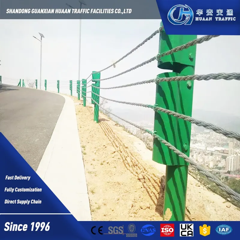
Cable Barrier for Bridge Edge
Cable barrier for bridge approaches and road edges, end-anchored into the structure. Supplied with anchors and brackets; site space is the deciding constraint.Specification parameters
1. Product Range
| Low-tension cable barrier | 3 cables on driven steel posts, end-anchored, with spring compensators |
|---|---|
| High-tension cable barrier | 3 or 4 pre-stretched ropes tensioned between terminals; posts in ground sockets |
| Multi-rope cable barrier | 5 or 6 ropes in Chinese class B / A designs |
| Terminals & anchors | Concrete end anchors with swaged threaded terminals and turnbuckles |
| Line posts & sockets | Intermediate posts held in sockets cast into concrete footings |
2. Wire Rope
| Construction | 3 × 7 zinc-coated steel wire rope, right-hand lay |
|---|---|
| Diameter | 19 mm (3/4 in) in published US and NZ specifications |
| Breaking strength | Min. 165.5 kN (one published manual); min. 173.5 kN (one US DOT specification) |
| Mass | Approx. 1.21 kg/m (19 mm rope) |
| Pre-stretching | High-tension rope pre-stretched to a specified minimum modulus of elasticity |
| Terminal fittings | Swaged threaded terminals, min. breaking strength 160.1 kN; stainless 304 swage fittings in one system |
3. Layout & Tension
| Rope heights | Bottom rope approx. 480 mm to top rope approx. 750 mm above ground, set by the system drawing |
|---|---|
| Post spacing | Chosen to limit dynamic deflection; one US DOT specification caps spacing at 4.9 m with deflection ≤ 3 m |
| Tension | Set from a temperature chart: e.g. 17 – 25 kN at 20 °C in one published manual; 20 kN initial tension (±5%) for Chinese class C / B / A cable barriers |
| Re-tensioning | Checked no sooner than 15 days after installation; re-tensioned below 90% of chart value |
| Run length | Up to 1200 m between end anchors; tension bays at ≤ 300 m centres |
4. Material & Surface Treatment
| Posts | Zinc-coated steel (ASTM A36 / Q235 class); sigma or round section |
|---|---|
| Post length | 1230 mm sigma post (one published system) |
| Rope | Galvanized wire rope to GB/T 25833 or AASHTO M30 Type I, Class A |
| Fittings | Hot-dip galvanized terminals, turnbuckles and anchor fittings |
| Plastic parts | UV-stabilised polypropylene |
5. Installation
| Line post footings | Cast-in-place concrete with socket; e.g. Ø300 × 600 mm in standard soil, Ø300 × 750 mm in weak soil |
|---|---|
| Concrete | Min. 25 MPa at 28 days |
| End anchor design load | Min. 66.7 kN horizontal per cable where anchored in separate foundations |
| Rope erection | Ropes strung after end-anchor concrete reaches 80% of design strength |
| Tolerances (JTG/T 3671-2021) | Initial tension ±5%; bottom rope height ±20 mm; post spacing ±20 mm; post plumb 10 mm/m |
6. Standards
| China | JT/T 895-2014 (cable barriers), GB/T 25833 (galvanized wire rope for highway barriers), JTG/T 3671-2021 (construction), JTG B05-01-2013 |
|---|---|
| USA | AASHTO M30 (wire rope), MASH / NCHRP Report 350 |
| Europe | EN 1317-2 |
| Australia / New Zealand | AS/NZS 3845.1:2015 |
7. Containment Level (as defined by the standard)
| EN 1317-2 working width | W1 ≤ 0.6 m, W2 ≤ 0.8, W3 ≤ 1.0, W4 ≤ 1.3, W5 ≤ 1.7, W6 ≤ 2.1, W7 ≤ 2.5, W8 ≤ 3.5 m |
|---|---|
| MASH (USA) | TL-1 50 km/h, TL-2 70 km/h, TL-3 100 km/h (1100 kg car, 2270 kg pickup); TL-4 adds a 10 000 kg truck at 90 km/h |
| JTG B05-01-2013 (China) | C 40, B 70, A 160, SB 280, SA 400, SS 520, HB 640, HA 760 kJ |
8. Applications
| Medians | Prevention of cross-median crashes, including wide medians |
|---|---|
| Roadside | Roadside and median runs on highways |
| Bridge approaches | Requires a transition where the cable run meets the bridge railing |
| Low-speed roads | Low-tension 3-cable systems limited in one US state to roads of 70 km/h (45 mph) or less |